Design and compatability
The sensor has two separate outputs: a normally opened dry relay contact and an analogue output 0…10 V (this output is adjustable for 2…10 V/0…20 mA/4…20 mA). The relay output is used to turn the fan on/off depending on indoor CO2-concentration and the analogue output is used for smooth fan speed control for a fan with EC-motor or a fan with extra speed controller with 0-10 V input. In case of smooth fan speed control, the fan speed varies proportionally to carbon dioxide emissions. The relay and analogue outputs make the sensor compatible with any ventilation system. The integrated self-calibration system ensures reliable sensor operation during the sensor service life.
Mounting and power supply
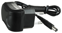
The sensor is designed for wall surface mounting. 24 VAC low current power supply. If power supply 24 V is not available, connect the TRF plug that is offered as an accessory.
Accessories

Power supply unit is applied for connection of the sensor to 120 V (TRF-120/24-1.6) AC power mains.
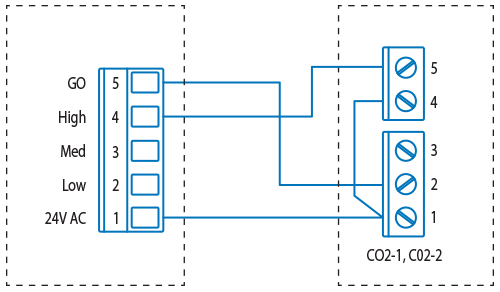
Wiring diagram
HRV/ERV External terminal

Modifications
The sensor is available in two modifications: CO2-1 and CO2-2. The CO2-1 model incorporates LED lights for CO2 concentration and operation buttons indicating the level of three operation modes: 1 — on, 2 — off, 3 — operation by CO2 concentration. The button is used to switch the ventilation system on or off when CO2 — based ventilation control is not required. The CO2-2 model has no LED-lights and on/off button. The model is applied for premises requiring permanent ventilation, i.e. at school classes and other public premises.
Mounting and power supply
| PARAMETERS | VALUE |
| Power supply / consumption | 24 VAC (50/60 Hz ± 10%), 24 VDC/1.6 W Max |
| Gas detection analyzer | Non-dispersive infrared detector (NDIR) with self-calibration system |
| CO2 measuring range | 0-2,000 ppm (parts per million) |
| Accuracy at 25 °C, 2,000 ppm | ±30 ppm + 3 % of reading |
| Response time | max. 2 min |
| Warm up time for each turning-on | 2 hours (first time), 2 minutes (operation) |
| Analogue output | 0-10 VDC (default), 4-20 mA selectable by jumpers |
| On/Off output | 1X2 A switch load. Four set points selectable by jumpers |
| 6 LED lights for CO2 concentration indication (for model CO2-1) | 1st green indicator lights when CO2 concentration is below 600 ppm;
1st and 2nd green indicators light when CO2 concentration is 600-800 ppm; 1st yellow indicator lights when CO2 concentration is 800-1200 ppm; 1st and 2nd yellow indicators light when CO2 concentration is 1200-1400 ppm; 1st red indicator lights when CO2 concentration is 1400-1600 ppm; 1st and 2nd red indicators light when CO2 concentration is above 1600 ppm |
| Operating conditions / storage recommendations | 0-50 °C; 0-95 % RH non condensing/ 0-50 °C |
| Weight / Dimensions | 0.120 kg/100 mm x 80 mm x 30 mm |
| Controls compatibility | CO2 Sensors
СO2-1 | Humidity sensor (NO)
HR-S | Control panel
P3-1-300 | Control panel
AC208EM2 +LP | Timer
A50 | Control panel pGDe |
| Products |
|
|
|
|
|
|
| TwinFresh Expert RA1-50-2 | + | + | - | - | - | - |
| TwinFresh Expert RW1-50-2 Wi-Fi | + | + | - | - | - | - |
| FRESHBOX 100 Wi-Fi | + | + | - | - | - | - |
| DVUT 300 HB EC A21 | - | + | - | - | - | - |
| DVUT 500 HB EC A21 | - | + | - | - | - | - |
| Brig HRV 120, 170 | + | + | + | + | + | - |
| Brig HRV/ERV 200, 300 | + | + | + | + | + | - |
| Frigate ERV 80R | + | + | + | + | + | - |
| Frigate HRV/ERV 120R | + | + | + | + | + | - |
| Frigate HRV/ERV 150R | + | + | + | + | + | - |
| Frigate ERV 80R EC | + | + | + | + | + | - |
| Frigate HRV/ERV 120R EC | + | + | + | + | + | - |
| Frigate HRV/ERV 150R EC | + | + | + | + | + | - |
| VUT/VUE 350 VB EC
A21/A22/A25 | + | + | - | - | - | - |
| AIRLITE HRV/ERV 8 | + | + | + | + | + | - |
| AIRLITE HRV/ERV 17 | + | + | + | + | + | - |
| AIRLITE HRV/ERV 25 | + | + | + | + | + | - |
| AIRVENTS RH | - | - | - | - | - | + |
| AIRVENTS RV | - | - | - | - | - | + |
| AIRVENTS RP | - | - | - | - | - | + |
| AIRVENTS CFP | - | - | - | - | - | + |
| AIRVENTS CFH | - | - | - | - | - | + |
| AIRVENTS CFV | - | - | - | - | - | + |